
Hello world!
Há um ano
The difficulties of installing an HI-FI system in a car are many, although there is no doubt that the most important is the limitation of the vehicle supply voltage. As most readers already know, the nominal voltage of a car battery is 12V, reaching about 13.8V when charging (i.e., engine running).
The maximum RMS. audio power from a given voltage V is somewhat less than:

Thus, for a 13.8V system, this power is limited to about 6W on a 4 Ohm load. Note that the lower the resistance of the speaker, the higher the maximum power (this is the reason most audio speakers have a 4 Ohm nominal impedance instead of the more common 8 Ohm in home systems).
This may be simplified to some extent ...P = (V / 3)2 / RL and a typical calculation based on a 13.8V supply gives
P = (13.8 / 3)2 / 4
P = 4.62 / 4 = 5.29 WattsThis allows for standard losses, and is acceptably accurate at this voltage - the only real way to know is to measure the amp, since the losses vary depending on the topology of the output stage in particular.
Power output can be increased by a factor of nearly 4 by using bridging techniques, explained in more detail in ESP project 14, so we can obtain up to about 24W on a 4 Ohm speaker. This can be enough for the midrange and high frequencies, but is obviously very limited for a subwoofer application, for example. (moral: distrust of "4 x 45W" head units is well advised, for they certainly aren't talking about RMS power).
So, what can be done to increase available audio power? The answer is a simple derivation of the above formula - either decrease load impedance or increase supply voltage. The lower the impedance, the more current is needed, making the construction of low impedance output stages more difficult (there are some other practical limits), so let's increase supply voltage.
The vast majority of high-powered audio amplifiers use SMPS (Switch Mode Power Supplies) to generate higher voltages from the available 12 (13.8) volts. An extensive theoretical explanation on how these things work is beyond the scope of this article, but these are some fundamental ideas you should know about switch mode power supplies (SMPS) for car amps:
At this point, the reader should realise the magnitude of the currents involved in a high power SMPS for a car amplifier, and that extreme caution should be taken especially when connecting "the creature" to the car electrical system.
The present project describes the construction of a flexible SMPS capable of delivering powers in the order of 350W continuously, depending on the transformer used. The output voltage depends mainly on the turns ratio of the primary and secondary windings, but may be adjusted to a somewhat lower value using regulation. This should be enough to power a 200W subwoofer amplifier plus perhaps 2 stereo amps for the mids and highs.
It is part of a complete car amp that I have built, with 6 power stages based on National's LM3886 Overture Amplifier. They can be combined into one >250W/4 Ohm subwoofer channel plus 2 x 65W/4 Ohm mid+high channels, alternatively into 2 x 120W/4 Ohm + 2 x 65W or even to form a multichannel 6 x 65W/4 Ohm amplifier, so it is an extremely flexible and high-powered system without renouncing sound quality. The parallel bridging techniques needed to do this will be possibly described in another project.
The complete schematic of the SMPS is shown below.
Note: This is Sergio's original version of the supply, the one shown in Figure 9 is likely to be the most commonly used, as it is somewhat simpler, but has virtually identical performance. [esp]

There are three main blocks described below ...
A - Switching MOSFETs and transformer
B - Rectification and filtering
C - Control circuitry
A - Switching MOSFETs and Transformer
The selected switching topology is called a "push-pull" converter, because the transformer has a double primary (or a "centre-tapped" one, if your prefer). The centre tap is permanently connected to the car battery (via an LC filter to avoid creating peaks in the battery lines, which could affect other electronic equipment in the car). The two ends of the primary are connected to a pair of paralleled MOSFETs each that tie them to ground in each conduction cycle (Vgs of the corresponding MOSFET high).
These MOSFETs should be fast, able to withstand high currents (in excess of 30A each if possible) and have the lowest possible Rds(on). The proposed On-Semiconductor’s MTP75N06 can withstand 75Amp and has a Rds(on) below 10 milliohm. This is important, because the lower this resistance is, the less power they are going to dissipate when switching with a square waveform. Another alternatives are MTP60N06, or the more popular BUZ11 and IRF540.
Although the schematics show a previous bipolar push-pull stage, you can also connect the gate resistor directly to the output of the controlling IC, leaving out the transistors, as the SG3525 is capable to drive up to 500 mA (theoretically), more than enough to switch the MOSFETs fast.
B - Rectification and Filtering
If one looks to the secondary side of the SMPS, it resembles exactly the scheme of a typical mains PSU, with one fundamental difference - the switching diodes have to be FAST or ULTRAFAST, if you use a standard diode bridge the system will simply blow up (and this can be very impressive, believe me!) Although a diode bridge is represented, it can be made with discrete diodes as well. Use high current (10 A minimum and a suitable voltage rating) diodes. I recommend using 4 x TO220 double diodes that can be paralleled to form a single one in each package.
You may be surprised that the capacitors aren't too big. This is due to the high switching frequency. It is important that they are good quality ones and must be rated for 105 degrees operation. Ripple current rating and low ESR (equivalent series resistance) is very important for any switching supply. In my opinion, 5000uF per rail is enough.
C - Control Circuitry
The controller IC is an SG3525. It comprises all the necessary subsystems to generate a fixed frequency, compare with a reference to modulate its pulse width and drive two outputs without overlapping. It works from 8 to 35V and filtering in the supply is recommended, as shown. As stated above, you can connect the outputs directly to the gate resistors of the MOSFETs if you don't want to include the bipolar stages.
The resistor RT and capacitor CT fix the oscillation frequency. Experimentation showed me that about 35kHz produces good results with my transformer. Another capacitor, Css fixes the "slow start" time - when you turn on the system, the pulse width increases from 0 up to the steady value, thus limiting the "inrush" current, a very good feature to avoid "thumps" in the speaker and protect the electrical installation. It has also a shutdown pin that allows control of the SMPS from an external signal (REMOTE from the head unit, for example).
In this project, layout is critical, incorrect track widths or excessively long traces can have high inductances and produce peaks that can make the MOSFETs blow up. ESP will probably offer a suitable PCB layout if there is enough interest in it.
This is the most critical part of the design, and you have two options, buying a commercial unit with the required power rating and turns ratio (hard to find, only a single supplier found at the time of writing), or wind your own.
If you choose to wind your own transformer (as if you have much choice), you have to decide which shape of core to use. The preferred material is ferrite, which has high permeability (ability to "conduct" magnetic flux) or iron powder, which has a lower permeability, but is less likely to saturate. Most commercial transformers use ferrite, and iron powder is generally the best material for filter chokes (inductors) that carry substantial DC.
For example, with a standard ETD39 core you could theoretically build a > 350W supply. Winding this type of cores is not very difficult, but you will have to follow some guidelines I provide below in order to have good results.
Another possibility is using a toroid. You can extract it from a BIG power inductor. As a guide, a 4cm diameter toroid with a section of about 1cm2 can be used for a > 250W SMPS. Winding is a little bit more complicated than with ETD cores but with a little practice is not too difficult either.


ETD-type cores

Toroid from ITL 100 inductor (Wilco Corp).
(Remove the thick wire before winding! :-)
These are a few general winding guidelines for all types of cores:
The following are photos of two models of transformers. The left one is a toroidal I wound myself using the core from a big inductor from Wilco Corporation (ITL-501), and the right one is a commercial unit from a US manufacturer (2x3:1, 350W). Both worked similarly.


Other remarks


Note the insulation pad (one for all) and the thick supply wires. Individual insulation pads may be used with no loss of performance. Use of a clamping bar will give improved thermal conduction to the heatsink bracket, but do not over tighten, or the bracket will bend.
This project handles quite large powers, so it is well worth the pain of step-by-step testing before you regret blowing all your work up in a microsecond.
For the tests, use a big 12V to 13.8V power supply, with current limiting if possible and capable of delivering at least 10 to 20 amperes (see project 77). If you don't have that, a PC computer PSU will work (although you won't get more than 80-90W, but it is enough for testing purposes and almost indestructible). Don't connect the SMPS to a car battery the first time you test it (it can be really dangerous!). A 10A fuse in series with the 12V supply is also a good idea. (You don't know to what extent! ;-)
The cables from the supply to the amp should be as short as possible and heavy gauged, to minimise losses. First time I tested the amp I had a 1 volt of difference from one side to the cable to the other in only 1.5 metres: the cable itself was dissipating more than 15W!!!. So, when calculating efficiency, always measure input voltage just at the input of the SMPS to account for this.
When you are completely sure that everything works as expected, you can proceed to connect it to the car electrical wiring (see "installation procedures" paragraph). First time you will notice an spark due to the sudden charge of the big input capacitor, unless you connect a resistor in series first (very good practice) to allow it charging slowly and then remove it for normal operation.
For your car and own safety, it is VERY IMPORTANT that you pay special attention when installing the power supply (and amplifier) in your car. These are some recommendations that everyone should follow carefully:
The project itself has excellent load regulation, and the rails voltage is almost only determined by the turns ratio, but it has inherently zero line regulation (basically, it "simply" multiplies the input voltage by the turns ratio), although this is not a problem in a car, where the battery voltage remains essentially constant.
If the obtained output voltages are very high and you can't (or don't want to) modify the windings, you can use regulation to lower them a bit. For example, I use a 3:1 transformer that would give about +/-38V without regulation that is unacceptable for my LM3886 stages to be safe, so I have regulated to +/-26V. The MOSFETs will suffer more, however, so regulate the supply only if strictly necessary.
You can install the feedback potentiometer and set it in order to have zero reference voltage to deactivate regulation, or increase its value to regulate to the desired voltage.
NOTE: Regulation will work better with output inductors just between the rectifier diodes and the output capacitors. 10 to 100 uH with iron powder core and at least 8A current rating can be adequate. (I don't use them and my supply works reliably, although I never put it to the power limits). You can also improve safety by paralleling more MOSFETs, so the current through them is shared. This also improves efficiency a bit, as the total Rds(on) is reduced.
If you need to power opamps for a crossover, equaliser or preamplifier, you can obtain a symmetrical +/-12V (for example) from the main supply rails, simply with a resistor, zener and capacitor. (see Figure 1 of Project 27). Remember to use 1 or 2W resistors and zener diodes. You can obtain about 25-50 mA from this without problems.
The following material is from ESP - there are some suggestions and additional information, as well as a simplified version of the SMPS.
Although my version of the switcher is simplified, this does not imply that performance is lower than Sergio's original, but is the result of my own experiments and tests. We may be on opposite sides of the planet, but there was considerable collaboration during the development of the supply, and I have built and tested the version shown below.
It has been claimed that MOSFETs are immune from thermal runaway, since they have a positive temperature coefficient for their "on" resistance. While this may be partially true for a Class-AB power amplifier, it is completely false for a switching supply.
For example, a push pull SMPS using one IRF540 MOSFET a side draws 30A at full load. If we check the data sheet, we find that Rds(on) is 0.044 Ohm (44 millohms) at 25 degrees C, then we know that it will generate
P=I² x R = 30%sup2; x 0.044 = 900 x 0.044 = 39 W peak (per transistor).At 50 degrees (not uncommon in a car that has been in the sun for some time), Rds(on) will be about 1.25 times the value at 25 degrees (this is from the datasheet), or 0.055 ohms. Power dissipation will now be 49W, so the heatsink has to dispose of more heat. We can guarantee that the extra heat will cause the heatsink temperature to rise further, which will increase Rds(on), and that will make the heatsink hotter, and … BANG
Ensuring that you use parallel devices and a good heatsink will reduce the likelihood of this dramatically. Two MOSFETs sharing the load will dissipate 1/4 the power (each) of a single device, and have a lower thermal resistance to the heatsink as well.
P=I² x R = 15² x 0.044 = 225 x 0.044 = 9.9 W peak (per transistor) - 19.8 W for both
The power shown per transistor is the peak - actual (RMS) power (per device) is half that calculated. The total power dissipated by both transistors (or sets of transistors in the case of paralleled devices) is the full value shown, since when one device is "on", the other is "off" and vice versa.
Naturally, the maximum dissipation will only occur at maximum (continuous) amplifier power - the real life requirements are usually somewhat less, however, it is essential that the design is capable of continuous "worst case" dissipation to ensure an adequate safety margin.
I strongly recommend that you do the calculations yourself, and make sure that you understand the implications.
Normally, one would expect regulation as shown in Figure 1, however, using the feedback input of the controller IC relies rather too heavily on the impedance of the DC supply lines. Normally, output inductors are used (with an additional "flyback" diode) to provide a pulse width to voltage converter. The majority of commercial systems seem to use a non-regulated converter, so I would consider that this will be quite acceptable in practice. Tests so far have shown that with a load of about 150 Watts, the regulation was almost entirely dependent on the voltage drop in the supply line!
As well as being unregulated, there are a couple of other changes in the circuit. R8 (100 Ohms) is connected between the timing capacitor and discharge pins of the controller IC. This introduces a "dead time" where both outputs are turned off, and the reason for this is to ensure that the power MOSFET pairs can never be switched on at the same time - should this happen, a very large current will flow (albeit for only a microsecond or less). Since I did not use the extra switching transistors and used higher value gate resistors, the dead time is important.
I also increased the switching frequency. As shown, the internal oscillator runs at approximately 50kHz (my prototype actually runs at 54kHz), where Sergio's original was designed for 35kHz switching. The difference is determined by the resistor on the RT pin of the controller, in my case, 12k.
Regulation will obviously make the circuit much more complicated, and as stated above, my version is unregulated. This will maintain maximum efficiency, and also reduces the dependence on the output filter capacitors - they are effectively fed with almost pure DC from the rectifier at all loads, so storage time is not an issue. Relatively small filter capacitors can be used, and the output will still be quite clean.
Not surprisingly, the turns ratio is very important if regulation is not used. Assume an input voltage of 12V to allow for losses. To obtain +/-24V, the turns ratio is 1:2 - for each turn on the primary, there will be 2 turns on the secondary. This is the same as Sergio's description, and the same rules apply. Unlike a normal mains transformer supplied with a sinewave, the switching waveform is a squarewave, so the peak and RMS values are the same (in other words, there is no 1.414 conversion as would be the case with a mains frequency transformer). The problem with this is that the 12V assumed at full load will be 13.8V under light or normal loading, so the voltage will be higher than expected. Using the same transformer as above (1:2 turns ratio) the no-load output voltage will be 27.6 volts - make sure that you do not exceed the voltage rating of the amplifier!

Since the transformer is relatively easy to wind, it is not a difficult task to dismantle it and add (or remove) secondary turns to get the voltage right. My prototype transformer used 5+5 turns for the primary, and I used 3 strands of 0.8mm winding wire twisted together. There is plenty of room in the recommended core, so it would be easy to use 5 strands instead for lower losses.
Note that in the above (Fig. 9), the the heavy leads shown carry substantial current, and must be sized accordingly. I do not recommend PCB traces be used, since the current involved is simply too high. Given that the suggested current density for PCB tracks is 4.0 A for a 100 "thou" (0.1" or 2.54 mm) track, then for 30A you need a track 0.75" (19 mm) wide! This is difficult to accommodate on any printed board.
I also eliminated the relay, but at the cost of a small current when the unit is not operating. The SG3525 has a shutdown pin for just this purpose. A signal from the remote head amp will turn on Q1, and remove the shut down signal from the controller. It behaves in exactly the same manner as if power had just been applied, and the unit will become fully operation in about 2 seconds or less. Current drain when turned off will be about 1 to 2mA - considerably less than the clock in the car. Battery discharge will not occur as a result of this very small current, which may be ignored as insignificant.
I recommend that an EDT39 ferrite core is used. These are easy to wind, and are capable of around 350W output. Bear in mind that this represents a considerable battery current at full power, in the order of 30 to 35 Amperes! Heavy transformer windings and supply cables are essential, and the input filter must be capable of withstanding this current without saturating the core.
The former for these cores is rather large, and you may decide to cut the mounting sections off completely. Do remember that the transformer must be mounted somehow though, so I suggest that you have a plan. At this stage, I am only experimenting, and do not have a plan. I will provide details of the solution when I actually have one.
All of Sergio's previous comments apply to this version, so make sure that you read his material thoroughly. I do not propose to cover the same instructions again, since Sergio has already done an excellent job.
I have done some initial tests, but have not yet connected the bridge and output capacitors. With what was intended to be 12+12 turns on the secondary, I obtained an acceptably clean waveform with some overshoot with the secondary unloaded. Output voltage was about 38V peak, so I obviously had one more turn than I thought I did (input voltage was 14V DC). I cannot stress highly enough that the winding process is critical to the success of your transformer, and you should expect to have a couple of attempts before you get it exactly right. The small number of turns needed makes this much easier than would otherwise be the case.
During my testing, my power supply and load became very warm indeed, but the MOSFETs (I used IRF540s) remained cool, even though they were mounted on a rather small heatsink lying on my workbench. This indicates that the heatsinking requirements are easily achievable, but does not mean that you can be lax with mounting. My transformer also remained cool, with no sign of the core or windings getting even warm. This must be considered a design goal. Even the lead I used to my load became warm, so the power output was very real indeed!
You will need an oscilloscope (or at least access to one) or the project will be very much harder to build and test. A design such as this relies on careful measurements and great care to make certain that it will perform as expected. Attempting this without an oscilloscope is not recommended.
This project has already created far more questions via e-mail than I desired or expected. For everyone who plans on making this supply ... you are essentially on your own. I cannot (and will not) be drawn into lengthy e-mail exchanges if you cannot make the supply work.
That it does work if built as described is certain, that you will be able to achieve the same results is not. If you do not have (or at least have access to) an oscilloscope - don't even think about trying to make the supply, as it will not be possible to ensure that the duty cycle of the controller is exactly 50%, or that there is no severe overshoot or ringing at the output.
Please do not not send me e-mails asking for help. I will simply refer you to this paragraph - I cannot diagnose your problems via mail, and will not even try. It is entirely up to the constructor to determine his/ her abilities before starting.
The construction of any switching supply is fraught with difficulties, risks (including but not limited to elecrocution!) and problems that need to be addressed. They are not simple (despite appearances) or easy, and there are a great many things that can go wrong. If you are not 100% confident that you understand the issues involved, please do yourself a favour and build something else instead.


"E" shapes used in "E-E" and "E-I" combinations became popular choices. "Scrapless" "E-I" patterns were developed. The electrical steel stamped out of two adjacent "E" laminations (placed leg end to leg end) to form the winding window area became the two "I" laminations to be placed across the leg ends of the "E" laminations. Since EI-core has two open coil sides, ferrite EI core provide substantial room to bring high current lead wires out from the coil. This also permits good heat dissipation. Ferrite EI core is easier to achieve high voltage electrical. EI cores are for mains transformers possess many benefits such as low noise, low magnetising current, fast assembly, and low cost.
EI-core is widely used in various kinds of power transformer cores, power inductor cores and chokes.
| Type | Dimensions(mm) | ||||||
|---|---|---|---|---|---|---|---|
| A | B | C | D | E | F | I | |
| EI12.5 | 12.5±0.3 | 7.4±0.2 | 5.0±0.2 | 2.4±0.2 | 9.1min | 5.1±0.2 | 1.5±0.15 |
| EI16 | 16.0±0.4 | 12.4±0.3 | 4.8±0.2 | 4.0±0.2 | 11.7 min | 10.4±0.3 | 2.0±0.2 |
| EI16A | 16.0±0.3 | 14.7±0.3 | 4.8±0.2 | 4.0±0.2 | 11.8 min | 10.8±0.2 | 2.0±0.2 |
| EI16B | 16.1±0.3 | 6.5±0.2 | 9.0±0.2 | 3.0±0.2 | 12.5min | 5.00±0.2 | 1.5±0.1 |
| EI19 | 19.2±0.4 | 13.6±0.4 | 5.1 +0 -0.5 | 5.1 +0 -0.5 | 14.0min | 11.0±0.3 | 2.4±0.2 |
| EI19A | 19.0±0.3 | 15.9±0.4 | 4.85±0.25 | 4.85±0.25 | 14.0±0.3 | 11.3±0.3 | 2.35±0.2 |
| EI22 | 22.2±0.3 | 14.4±0.25 | 5.75±0.25 | 5.8±0.3 | 12.8min | 10.5±0.3 | 4.5±0.2 |
| EI22A | 22.0±0.6 | 15.0±0.3 | 6.0 +0 -0.50 | 6.0 +0 -0.50 | 15.6min | 11.0 +0.6 -0 | 4.0±0.3 |
| EI22B | 22.0±0.6 | 14.6±0.3 | 6.0 +0 -0.50 | 6.0 +0 -0.50 | 15.6min | 10.6±0.3 | 4.5±0.3 |
| EI22C | 22.0±0.4 | 19.0±0.4 | 5.75±0.25 | 5.75±0.25 | 16.0±0.4 | 11.0±0.2 | 4.0±0.2 |
| EI25A | 25.4±0.5 | 16.3 +0.5 -0.1 | 6.8 +0 -0.5 | 6.6±0.3 | 18.6min | 13.0 +0.5 -0.1 | 3.0±0.2 |
| EI25B | 25.1±0.4 | 19.0±0.5 | 6.75±0.25 | 6.5±0.3 | 19.1min | 13.25±0.25 | 2.75±0.15 |
| EI28 | 28.0±0.4 | 20.8±0.4 | 10.7±0.3 | 7.2±0.3 | 18.6min | 12.8±0.2 | 3.5±0.15 |
| EI28A | 28.0±0.6 | 17.5 +0.3 -0.2 | 11.0 +0 -0.5 | 7.5 +0 -0.5 | 18.6min | 12.8 +0.3 -0.2 | 3.5±0.3 |
| EI28B | 28.0±0.6 | 16.75±0.25 | 11.0 +0 -0.6 | 7.25±0.25 | 18.6min | 12.25±0.25 | 3.5±0.3 |
| EI30 | 30.5±0.5 | 21.5 +0.6 -0.2 | 11.0 +0 -0.5 | 11.0 +0 -0.6 | 20.0min | 16.5 +0.6 -0 | 5.5±0.3 |
| EI30A | 30.0±0.6 | 21.25±0.25 | 10.7±0.3 | 10.7±0.3 | 19.5min | 16.5±0.25 | 5.5±0.2 |
| EI33 | 33.0±0.6 | 24.0 +0.5 -0 | 13.0 +0 -0.5 | 9.7±0.3 | 23.8min | 19.0 +0.5 -0 | 5.0±0.3 |
| EI33A | 33.0±0.6 | 23.5±0.5 | 12.7±0.3 | 9.7±0.3 | 23.6min | 19.0±0.5 | 5.0±0.3 |
| EI35A | 35.0±0.6 | 24.2±0.5 | 10.0±0.3 | 10.0±0.3 | 24.5min | 18.2±0.3 | 5.0±0.3 |
| EI35B | 35.0±0.6 | 24.2±0.5 | 11.7±0.3 | 10.0±0.3 | 24.5min | 18.2±0.3 | 5.0±0.3 |
| EI40A | 40.0±0.7 | 27.3±0.3 | 12.0 +0 -0.5 | 12.0 +0 -0.5 | 26.8min | 21.0 +0.7 -0 | 6.7±0.3 |
| EI40B | 40.0±0.7 | 27.2 +0.6 -0 | 12.0 +0 -0.5 | 12.0 +0 -0.5 | 27.5min | 11.0 +0.6 -0 | 7.5±0.3 |
| EI41 | 41.0±0.9 | 26.2±0.4 | 11.8±0.6 | 11.8±0.6 | 28.0min | 20.2±0.4 | 7.2±0.4 |
| EI50 | 50.0±0.7 | 33.35±0.35 | 14.6±0.4 | 14.6±0.4 | 34.0min | 24.75±0.3 | 9.0±0.3 |
| EI50A | 50.0±1.2 | 33.3±0.4 | 14.8±0.6 | 14.8±0.6 | 34.0min | 24.8±0.4 | 9.0±0.4 |
| EI60 | 60.0±0.8 | 35.85±0.35 | 15.6±0.4 | 15.6±0.4 | 44.1min | 27.85±0.35 | 8.5±0.3 |
| EI70 | 70.0±1.5 | 45.5±0.5 | 19.5±0.5 | 19.5±0.5 | 50.0±0.5 | 35.5±0.5 | 10.5±0.5 |
| Type | Core parameter | weight (g/pr.) | Al(nH/N²) | Pc(W) | |||||
|---|---|---|---|---|---|---|---|---|---|
| C1 (mm-1) | Ae (mm2) | Ie (mm) | Ve (mm3) | F2BD (±25%) | F2B1 (±25%) | F3 (±25%) | F2B1 (max.) | ||
| EI12.5 | 1.44 | 14.4 | 20.6 | 297.5 | 1.9 | 1200 | 1200 | 1300 | |
| EI16 | 1.84 | 19.7 | 34.9 | 685.3 | 3.3 | 1000 | 1000 | 1400 | |
| EI16A | 1.90 | 18.8 | 35.9 | 676 | 3.4 | 1250 | 0.42 | ||
| EI16B | 1.10 | 26.4 | 29.1 | 767 | 3.4 | 2300 | 0.38 | ||
| EI19 | 1.5 | 24 | 39.0 | 1028.2 | 5.0 | 1200 | 1200 | 1500 | |
| EI19A | 1.68 | 23.3 | 39.2 | 913 | 4.6 | 1300 | 0.55 | ||
| EI22 | 0.94 | 42.0 | 39.3 | 1630 | 9.8 | 2400 | 0.81 | ||
| EI22A | 1.1 | 40.1 | 42.3 | 1697.0 | 9.8 | 1800 | 1800 | ≥1600 | |
| EI22B | 0.94 | 42 | 39.3 | 1650.6 | 9.8 | 1900 | 1900 | ≥1700 | |
| EI22C | 1.15 | 37.0 | 42.5 | 1570 | 8.4 | 1950 | 0.95 | ||
| EI25A | 1.1 | 44.3 | 48.5 | 2145 | 9.8 | 1800 | 1800 | ≥1500 | |
| EI25B | 1.22 | 39.7 | 48.6 | 1930 | 9.8 | 1900 | 1.16 | ||
| EI28 | 0.586 | 84.4 | 49.5 | 4170 | 22 | 3800 | 2.51 | ||
| EI28A | 0.55 | 89.5 | 49.3 | 4399 | 22.0 | 3800 | 3800 | ≥3600 | |
| EI28B | 0.52 | 92.3 | 48.9 | 4515 | 22.0 | 3800 | 3800 | 4500 | |
| EI30 | 0.5 | 115.6 | 58.2 | 67341.1 | 34.0 | 4000 | 3700 | 4900 | |
| EI30A | 0.522 | 111 | 58.0 | 6440 | 34 | 4690 | 3.23 | ||
| EI33 | 0.57 | 124.9 | 67.3 | 8408 | 41.0 | 4200 | 4000 | ≥3900 | |
| EI33A | 0.570 | 119 | 67.5 | 8000 | 41 | 4400 | 4.0 | ||
| EI35A | 0.6 | 107 | 68.1 | 731.1 | 36.0 | 3500 | 3200 | 4200 | |
| EI35B | 0.5 | 126 | 68.1 | 8564 | 43.0 | 3200 | 3200 | 4400 | |
| EI40A | 0.5 | 150 | 76.5 | 11534 | 60.0 | 5100 | 4860 | 5400 | |
| EI40B | 0.5 | 153 | 76.3 | 11683 | 60.0 | 5100 | 4860 | 5400 | |
| EI41 | 0.533 | 145 | 77.0 | 11100 | 56 | 4860 | 6.45 | ||
| EI50 | 0.4 | 231 | 94.1 | 21759 | 115 | 6450 | 6100 | 7000 | |
| EI50A | 0.411 | 230 | 94.0 | 21600 | 115 | 6110 | 2.16* | ||
| EI60 | 0.4 | 272 | 111.8 | 30454.4 | 139 | 6250 | 5600 | 6400 | |
| EI70 | 0.37 | 390 | 133 | 51900 | 252 | 8070 | 6.23* | ||
As fontes de alimentação destinam-se a alimentar os circuitos com correntes contínuas.
Nos circuitos mais recentes, para além das fontes de alimentação convencionais, usam-se fontes de alimentação comutadas (Switching Power Supplies, Fontes Chaveadas). Este tipo distinguem-se das fontes convencionais pela sua capacidade de fornecer correntes mais elevadas sem transformadores de grande dimensão e pelo controle da corrente que determinado enrolamento no secundário pode fornecer.
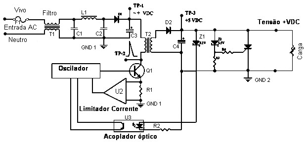
A fonte comutada tem 3 grandes estágios.
Primário:O primário é na verdade uma fonte convencional com rectificação e filtragem completo com uma secção rectificação básica e o filtro (D1/C3), que fornece tensão DC (contínua) para o circuito de comutação (T2/Q1).A Tensão CC é simplesmente aplicada a um terminal do enrolamento primário do transformador T2, com o outro terminal do transformador ligado ao colector do transístor de potência Q1. Este transístor funciona como elemento de comutação dos pulsos DC para criar "corrente contínua pulsante", que se irá comportar como AC no enrolamento secundário, devido à mudança do campo magnético. Com esta acção no sentido normal não irá funcionar no transformador - esta acção de comutação (chaveamento) basicamente converte o pulsar em DC DC, provocando mudança dos campos magnéticos que, por sua vez induz uma tensão no secundário do T2. A frequência que o transístor de comutação funciona é fornecida pelo (Oscilador / Pulser) é um aspecto extremamente importante para as tensões induzidas no secundário. Pense nisso deste modo - um pulso no primário = 2 tensões induzidas no secundário. Uma tensão induzida no secundário com o aumento do pulso, no primário (quando aumenta o campo magnético), e um pulso induzido no secundário quando o pulso se desliga (quando o campo magnético colapsa). Um pulso por segundo não iria gerar muita tensão no secundário, é igualmente evidente o fato de que quanto maior a frequência de oscilação, uma maior frequência será induzida no secundário.
Secundário:No secundário de uma fonte de alimentação comutada (chaveada) existem rectificadores e filtros (D2/C4) na Secção Secundária faz-se a conversão normal AC para DC pulsos em pulsos, e filtra-se para criar corrente contínua bem filtrada. Circuito de Controlo : Um método utilizado é o de comparar a de saída DC com a frequência dos pulsos que chega ao transístor de potência, que está no primário : Isto pode ser conseguido através de um Diodo Zener (Z1), em conjugação com um acoplador óptico (U1). Assumindo que a acoplador óptico é na verdade um LED, e projecta a luz para um Foto-Transístor, um aumento de tensão acima do limite estabelecido do diodo zener fará com que o LED inicie a condução. Neste exemplo, quando o LED acende menos, então o Foto-Transístor também irá conduzir menos, o que permitirá que a frequência dos pulsos entregue ao transístor de comutação aumente, e, assim, fazer com que o CC tensão de saída de ser possa ser aumentada . Existem vários métodos de fontes comutadas (chaveadas), todas elas têm esta a base, um oscilador no primário oscila, essa oscilação cria pulsos que através de um transformador permitem que díodos rectificadores e outros dispositivos reguladores alimentem o circuito a que se destinam. Existem diversos métodos de controlo e protecção que podem ser verificados, por exemplo, em fontes chaveadas para tv.
Fonte de Alimentação TV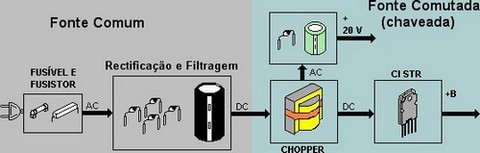 Fonte Comum Os díodos rectificam a tensão alternada da rede, o condensador de filtragem, em conjunto transformam a tensão para contínua de 150 V ou 300 V se a rede for 220 V. Esta tensão vai para a fonte comutada (chaveada). O fusistor de entrada tem duas funções:
As duas bobinas e o capacitor de poliéster na entrada da rede não permitem que a frequência da fonte saia pela rede e interfira em aparelhos circundantes. Circuito de desmagnetização - A bobina de desmagnetização fica enrolada numa fita isolante em volta do TRC. Tem a função de criar um campo magnético alternado com a tensão da rede para desmagnetizar a máscara de sombras. Desta forma evita-se que a imagem apresente manchas coloridas nos cantos da imagem. Esta bobina funciona por poucos segundos até que o termistor PTC aqueça, aumente sua resistência e diminua bastante a corrente. Fonte Comutada em série Neste tipo circuito, um transístor (regulador) fica em série com a linha +B. O transístor recebe +B da fonte comum através do primário de um transformador de ferrite (chopper). Através da oscilação deste transformador juntamente com alguns componentes ligados, o transistor funciona como uma chave (ON/OFF), conduzindo e cortando cerca de 15.000 vezes por segundo. Quando conduz, carrega o condensador(capacitor) da saída com 100 V. Quando corta, a tensão do condensador (capacitor) mantém o TV com alimentação. Quando se liga o TV, R2 polariza a base do regulador e este conduz, fazendo passar corrente no chopper que induz um pulso no secundário, sendo aplicado na base através de R3 e C3. O regulador então corta, interrompe a corrente, e o chopper induz outro pulso para a base fazendo o regulador conduzir novamente e este ciclo repete-se. A fonte comutada(chaveada) pode por isso auto denominar-se fonte auto oscilante. O +B na saída desta fonte já está estabilizado e vai alimentar o circuito horizontal do TV. Fonte Comutada em série com CI No pino 3 entra o +B não estabilizado da fonte comum e no pino 4 sai o +B estável. O pino 2 tem três funções: disparo inicial, oscilação e sincronismo da fonte com o circuito horizontal do TV através de pulsos de 15.750 Hz vindos do transformador de linhas(Flyback-LOPT). Observe como os componentes que mantém a tensão estável na saída da fonte ficam todos dentro do STR. Neste exemplo, como ocorre em várias TVs, o chopper além de manter a oscilação da fonte, também fornece uma tensão que será retificada e alimentará outros circuitos. O condensador(capacitor) CF entre os pinos 3 e 4 elimina os ruídos gerados pelo comutação do CI. Esta fonte já é bivolt automática. Quando o TV é ligado em 220 V, a fonte comum fornece 300 V para o pino 3 do STR, mas muda a frequência de oscilação e mantém as mesma tensão no pino 4. Fonte Comutada em paralelo com STK O CI é o STK79037 (STK79038) ou IX1791 de 12 pinos. Ao ligar o TV, o pino 5 recebe o +B da ponte rectificadora, através do resistor de disparo, alimenta o gate do MOSFET comutador interno e a partir daí a fonte começa a oscilar. Os pinos 1 e 3 recebem uma amostra da tensão da saída através do regulador SE115 IC3 e do fotoacoplador IC2. Assim podem alterar a frequência e o valor do +B caso exista necessidade de forma idêntica à fonte que usa o CI STR de 9 pinos. Fonte chaveada em paralelo com Mosfet O transístor desta fonte é um MOSFET que consome menos energia que um transístor comum para a mesma função. O oscilador e o controle da fonte estão dentro do IC1. Ao ligar o TV, os pinos 2 e 6 recebem uma tensão inicial de disparo e a fonte começa a oscilar. O MOSFET recebe a tensão de entrada no dreno (D) e o sinal PWM no gate (G). O source (S) liga a terra. Assim, existe comutação entre o primário do chopper que transfere a tensão para os secundários originando os +B da fonte. O pino 1 verifica os +B e ajusta a frequência do CI para efectuar a correcção da fonte quando necessária. Também é possível mudar a frequência da fonte e o valor dos +B manualmente através de uma resistência ajustável ligada no pino 1. O diodo D2 e componentes associados a formam um circuito chamado snubber com duas funções:
Fonte Chaveada em paralelo com STR A tensão da fonte comum entra no pino 1 onde está o transistor comutador com tem ligações fora do CI pelos pinos 1, 2 e 3. O CI gera os pulsos PWM internamente, saindo pelos pinos 4 e 5 e indo para a base do comutador (pino 3). O pino 9 do CI recebe dois +B: Um deles vindo da ponte rectificadora para o disparo da fonte e o outro rectificado e estabilizado pelo transistor Q1, mantendo o CI alimentado. Estabilização do +B - O fotoacoplador IC2 e o regulador IC3 retiram uma amostra do +B e enviam ao pino 7 do STR. Desta forma verifica como está a tensão na saída da fonte. Quando o +B aumenta, o LED do fotoacoplador acende mais intensamente e aumenta a tensão no pino 7 do STR. Isto aumenta a frequencia do oscilador interno do STR, fazendo o comutador cortar a uma frequência mais elevada reduzindo a tensão induzida no secundário do chopper, assim, o valor do +B volta ao normal. Defeciências no IC2 ou IC3 pode deixar o +B muito baixo ou muito alto. Componentes comuns nas fontes de alimentação de televisão
| |||||||||||
Um transformador toroidal funciona baseado nos mesmos princípios de outro transformador com núcleo laminado comum, porém com diferenciais que o tornam superior. Essas vantagens são conhecidas e reconhecidas globalmente por inúmeras empresas.
A palavra toroidal refere-se à forma geométrica do núcleo, no caso, redondo e semelhante a um anel. Podemos considerar o núcleo como o coração do transformador. Ele pode ser constituído por diversos materiais magnéticos, desde uma fita muito fina de aço silício com grão orientado (G.O. - especial), até materiais advindos da nanotecnologia. Isso resulta em uma imensa gama de produtos que podem se beneficiar das potencialidades deste tipo de transformador.
Principais características:
Comparados aos transformadores comuns (E/I por exemplo), nossos transformadores toroidais fabricados em aço-silício GO, oferecem importantes vantagens, dentre elas:
`
- Baixíssima irradiação do campo magnético ao redor do transformador, não
afetando circuitos eletrônicos sensíveis, sejam eles analógicos ou digitais;
- Baixíssimas perdas, o que proporciona um menor consumo pois a corrente
consumida em vazio (sem carga) é bastante pequena.
- Menor variação de tensão na saída de potência, ou seja, a diferença entre a tensão
de saída com carga e sem carga (em vazio) é inferior a de um transformador convencional.
- Tamanho Reduzido, em geral, entre 40 e 60% menores e mais leves que os
transformadores convencionais;
- Flexibilidade de Projeto: ao contrário dos transformadores convencionais, o
toroidal adquire formas muito mais adaptáveis as necessidades do projeto;
- Fácil montagem em equipamentos, podendo ser fixado com apenas 1 parafuso ou
ainda com pinos (para PCB) ou abraçadeiras plásticas, reduzindo tempo de montagem.
- Funcionamento silencioso, ou seja, o ruído mecânico da vibração do núcleo
praticamente não existe.
Por isso, um transformador toroidal, quando corretamente dimensionado, projetado e fabricado, pode ser considerado o "Rolls Royce" dos transformadores elétricos.
Vantagens da ausência de GAP:
Uma das vantagens do transformador toroidal vem do fato de que o núcleo não possui GAP, ou simplesmente aberturas (cortes) no núcleo. Na maior parte das aplicações, estes GAPs são buracos para o fluxo magnético (linhas de campo), aumentando sensivelmente as perdas. No transformador toroidal, o núcleo é homogêneo, sem cortes e com uma geometria tal que o torna absolutamente mais eficiente.

Somado a isso, os transformadores de potência que utilizam núcleo de aço-silício, recebem um material superior, chamado de grão orientado (GO), podendo ser até 3x mais fino que o material usado em transformadores convencionais (E/I por exemplo), resultando a obtenção de maior performance do produto.
Menor variação de tensão:
Em qualquer transformador de potência será observado uma diferença entre a tensão com a carga máxima e sem carga. Em alguns circuitos eletrônicos, essa variação pode ser prejudicial. Devido as baixas perdas do transformador toroidal, a queda de tensão é bastante reduzida, podendo reduzir também a energia dissipada por alguns componentes eletrônicos.
Menor temperatura de trabalho:
A temperatura de operação de um transformador é um item de segurança que deve ser levado em conta durante um projeto. Nossos transformadores toroidais são calculados para operar em locais com temperatura ambiente de até 50 °C. Quando especificado, podemos fornecer para ambientes ainda mais severos. Devido as pequenas perdas no núcleo, a corrente de consumo em vazio é baixa (menor consumo de energia), o que proporciona uma menor elevação de temperatura. Quando a potência de saída é exigida em um ciclo de trabalho reduzido, é possível eliminar eventuais sistemas de ventilação forçada.
, acompanhe o gráfico:

Com 50% da potência máxima de saída, a elevação de temperatura será de apenas 25%.
Irradiação magnética ultra baixa:
Nossos transformadores toroidais já possuem uma irradiação magnética consideravelmente baixa quando comparado com transformadores comuns. Porém para aplicações sensíveis, podemos ainda adicionar uma blindagem magnética ao redor do transformador, diminuindo qualquer possibilidade de interferência eletromagnética (EMI) em circuitos sensíveis. Isso auxilia especialmente no cumprimento das mais exigentes normas técnicas (CE,UL, TÜV, CSA, etc).
Blindagem eletrostática:
Trata-se de uma blindagem eletrostática utilizada para diminuir a corrente de fuga entre enrolamentos primários e secundários (diminuindo o acoplamento capacitivo). É especialmente indicada onde há necessidade de baixas correntes de fuga entre enrolamentos, como em equipamentos médicos que requerem maior segurança ao paciente. Essa blindagem é formada por uma camada condutiva entre enrolamentos primários e secundários, e deve ser conectada ao aterramento da rede elétrica. Essa blindagem é altamente recomendada também para redes elétricas expostas a descargas atmosféricas (raios).
Critérios de fabricação:
Nossa produção é basicamente customizada, ou seja, projetamos e fornecemos conforme a especificação de cada cliente, agregando mais essa vantagem ao transformador.
Todos os transformadores toroidais são construídos dentro da Classe A de temperatura (105ºC) com isolamento de 2 kV entre o enrolamento primário e secundário (exceto os auto-transformadores), Classe B (130 °C), isolamentos até 6 kV ou ainda especificações superiores podem ser obtidos mediante especificação.
Deve-se esclarecer que, em todos os casos, o isolamento do fio de cobre utilizado suporta temperaturas de até 180 ºC ou 200 ºC, em sua maioria possui dupla camada de verniz (grau reforçado).
Sobre o ciclo de trabalho de um transformador:
Pode-se reduzir o tamanho e o custo de um transformador se o seu ciclo de trabalho é curto. Por exemplo: um transformador de 100 VA usado com carga máxima apenas durante curtos intervalos de tempo, será menor que outro, também com 100 VA, que é usado com carga máxima durante muitas horas. Por isso, quando especificar transformadores, mencione o ciclo de trabalho.
Sobre a corrente de partida ou “in rush”:
Um cuidado que deve ser tomando é quanto a corrente no momento em que um transformador toroidal de potencial é energizado: devido à grande propriedade magnética do aço GO (grão orientado), a corrente de magnetização (denominada também de corrente in rush e que aparece apenas durante poucos milisegundos) é bem maior que a corrente nominal de trabalho. Sendo assim, recomenda-se a utilização de fusíveis do tipo retardado ou o uso de PTC's (ou resistores) em série com o primário. Em transformadores menores essa propriedade não é tão perceptível. Porém, nos maiores (em geral, nas potências acima de 1000 VA), o projetista deve tomar esses cuidados para não danificar chaves de ligação ou dispositivos de proteção ligados aos enrolamentos primários.
Verdades e Mentiras Sobre os Transformadores Toroidais:
- No transformador toroidal a corrente em vazio é até 90% menor que nos modelos convencionais (E/I)?
VERDADE. Devido a sua forma construtiva e materiais utilizados, um transformador toroidal não aquece quando está em repouso (sem carga). Isso obviamente economiza energia elétrica, especialmente quando o transformador fica ligado 24 horas por dia.
- O transformador toroidal usa materiais especiais na fabricação?
VERDADE. Para ter um rendimento superior, é fundamental que sejam utilizados materiais especiais, como o aço silício grão-orientado (GO) para fabricação do núcleo. Também o fio de cobre e os materiais isolantes empregados na construção, devem atender classes específicas, especialmente quanto à temperatura. Além dos materiais, o processo de fabricação deve ser controlado, como por exemplo, o tratamento térmico no núcleo, os ajustes de máquina e os procedimentos de teste. Sem isso, a segurança e o rendimento do transformador toroidal ficam comprometidos. Por isso, a Toroid do Brasil tem se destacado junto aos clientes, devido à seriedade e qualidade com que produz transformadores.
- Todos os transformadores toroidais são muito caros, se comparados aos modelos convencionais?
MENTIRA. Apenas transformadores toroidais PEQUENOS é que são mais caros. O processo construtivo de um toroidal é bem mais complicado do que em transformadores convencionais, tornando o processo mais caro. Porém, essa diferença é sensível apenas para modelos pequenos, abaixo de 100VA. A medida que a potência aumenta, a diferença de preço entre o toroidal e o convencional diminui. Para algumas aplicações, como iluminação, a partir de 300VA os toroidal já estão competitivos inclusive em preço. E, a partir de 1000 VA, o transformador toroidal é imbatível em preço. Explica-se: embora para o toroidal, o processo de fabricação seja mais demorado e os materiais melhores – o que torna o conjunto mais caro – em transformadores maiores a diferença de peso e tamanho é tão grande, devido ao toroidal usar bem menos material que o modelo convencional, que acaba compensado e o preço final é menor. Mas, mesmo para transformadores pequenos, em algumas aplicações onde é exigido baixo peso ou baixa altura do transformador, ou ainda, uma confiabilidade e segurança maiores – como em equipamentos médico, por exemplo – os clientes tendem a usar toroidais, mesmo sendo um pouco mais caros que os convencionais.
- Um transformador toroidal pode ter os enrolamentos danificados devido a vibração excessiva?
MENTIRA. Esse talvez seja o maior engano de alguns céticos. Talvez por terem experimentado toroidais feitos artesanalmente no passado, por fabricantes inexperientes ou que usavam materiais de baixa qualidade. Mas, após a chegada da Toroid do Brasil ao mercado nacional, elevou-se em muito o padrão de qualidade, pois usamos materiais certificados internacionalmente, além de máquinas específicas para enrolamento de toroidais. Fabricamos transformadores de 20 g até quase 50 kg, para uso em aplicações tão severas como trios elétricos, aviões, robôs submarinos, geradores elétricos (motor Diesel ou gás) e rastreadores veiculares (módulo junto ao motor), todos com alto índice de vibração ou esforço mecânico/térmico. Quando corretamente construído, um transformador toroidal é tão resistente quanto qualquer outro equipamento elétrico, estático ou girante (motores).
Os toroidais são denominados transformadores ou indutores de modo comum ou diferencial, porém sua dispersão magnética é menor do que um núcleo de ferrite convencional. Os transformadores toroidais produzidos pela Multitrafos, são de alta qualidade, sobre tudo no processo de enrolamento do núcleo. Para fabricação dos transformadores toroidais utilizamos maquinário sofisticado, o que permite a uniformidade do enrolamento do fio.
Nos projetos customizados, os núcleos especiais podem ser produzidos com dimensões que atendam às necessidades dos nossos clientes. No núcleo Toroidal, o fluxo trabalha na mesma direção do aço e sem nenhuma resistência, pois não tem "gaps", o que também diminui consideravelmente o campo magnético irradiado. Além disso, como o núcleo não precisa de parafusos para segurar o aço, o ruído mecânico é extremamente baixo, além de um produto mais leve e compacto.
Ao solicitar um transformador ou indutor toroidal, é importante especificar a nossa equipe de desenvolvimento de projetos, qual o ciclo de trabalho do toroidal. Com isso confeccionaremos um transformador toroidal que se encaixe perfeitamente às necessidades do seu projeto, podendo com isso, até diminuir o preço e o tamanho do mesmo.
As principais vantagens de um Transformador ou Indutor Toroidal:


 Figura 1 - Porta NAND ou NE TTL, com três entradas.
| A | B | C | Out |
| 0 | 0 | 0 | 1 |
| 0 | 0 | 1 | 1 |
| 0 | 1 | 0 | 1 |
| 0 | 1 | 1 | 1 |
| 1 | 0 | 0 | 1 |
| 1 | 0 | 1 | 1 |
| 1 | 1 | 0 | 1 |
| 1 | 1 | 1 | 0 |
 Figura 2 - Diagrama lógico do TTL 7410.
 Figura 3 - Lógica TTL com entrada normal versos entrada Schmitt trigger.
Circuito série: é aquele culos elementos são ligados um após outro, sendo que um elemento depende do outro e constitue uma malha elétrica. Esse circuito recebe o nome de dependente, porque se um dos elementos for interrompido os demais deixarão de funcionar; isto porque ele se compõe de um só ramo, ou seja, um só caminho para a passagem da corrente.
 |
Circuito paralelo: é aquele em que seus elementos são colocados um independente do outro. Isto quer dizer que, se um elemento qualquer deixar de funcionar, não perturbará o funcionamento dos demais.
Associação de resistores
Circuito série:
EXPERIÊNCIA:
Meios: Fonte de tensão U = 10 V; e resistores 18![]() - 1 W, 18
- 1 W, 18![]() - W, 68
- W, 68 ![]() -1 W, voltímentros, amperímetros, ohmímetros, fios.
-1 W, voltímentros, amperímetros, ohmímetros, fios.
Monte o circuito conforme o desenho.
 |
Medir os valores de U, R e I e conferir na tabela abaixo os valores encontrados.
| Observação | ||||
| ..... | (I) Medição | (II) Medição | (III) Medição | Total |
| U ( V ) | U1= 1,75 V | U2= 1,75 V | U3= 6,5 V | U= 10 V |
| I ( A ) | I1= 0,096 A | I2= 0,096 A | I3= 0,096 A | I= 0,096 A |
| R ( | R1= 18 | R2= 18 | R3= 68 | R= 10 |
Conclusão:
A resistência total num circuito série é igual á soma de todas as resistências oferecidas pelos resistores desse circuito.
A intensidade de corrente num circuito série é igual em todas as partes do circuito.
A intensidade de corrente num circuito série é igual em todas as partes do circuito.
OBS. : Para encontrar-mos um valor desconhecido de I, U ou R em qualquer circuito, primeiro empregamos as leis de Kirchhoff e depois a lei de Ohm.
Exemplo: Determine no circuito abaixo a resistência Rt, a corrente total I e as tensões parciais U1, U2 e U3. Dado: R1 = 50![]() ; R2 = 100
; R2 = 100![]() ; R3 = 70
; R3 = 70![]() e Ut = 220 V.
e Ut = 220 V.
Exercício 1: No circuito abaixo mede-se os seguintes valores: R1 = 20![]() ; Rt = 100
; Rt = 100![]() ; U = 24 V e U1 = 4,8 V.
; U = 24 V e U1 = 4,8 V.
Determine: U2 e I
 |
Circuito paralelo:
EXPERIÊNCIA
Meios: Fonte de tensão U = 10 V, 3 resistores, R1 = 10 ![]() - 10 W, R2 = 20
- 10 W, R2 = 20 ![]() - 5 W, R3 = 68
- 5 W, R3 = 68 ![]() - 2 W, voltímetro, fios, ohmímetros.
- 2 W, voltímetro, fios, ohmímetros.
 |
Execusão:
Meça os valores de U, I e R conforme indicado no circuito ao lado e configura os valores na tabela.
| ...... | ( I ) Medição | ( II ) Medição | ( III ) Medição | Total |
| U ( V ) | U = 10 V | U = 10 V | U = 10 V | U = 10 V |
| I ( A ) | I = 1,0 A | I = 0,5 A | I = 0,147 A | I = 1,66 A |
| R ( | R = 10 | R = 20 | R = 68 | R = 6 |
Execusão:
Meça os valores de U, I e R conforme indicado no circuito ao lado e configura os valores na tabela.
Conclusão:
A tensão no circuito paralelo é a mesma em todas as partes do circuito.
Ut = U1 = U2 = U3 = ... = Un
A corrente que chega a um pnto no circuito é igual á soma das correntes que dele saem, ou vice-versa. É definido pela 1ª lei de Kirchhoff.
It = I1 + I2 + I3 + ... + In
A resistência total Rt de um circuito elétrico ligado em paralelo é menor do que a resistência oferecida pelo menor resistor do circuito. Para se calcular a resistência total Rt de um circuito paralelo, aplicamos as fórmulas da lei de Ohm. Sabendo-se que a f´rmula para calcular It do circuito paralelo é: It = I1+ I2 + I3 + . . . + In
Substituindo I Por![]() temos :
temos : ![]()
Simplificando, temos :![]()
Fórmula geral ![]()
Exemplo: Cálculo da resistência total Rt na experiência anterior.
 |
O resultado é o mesmo que foi medido.
Fórmula específica para calcular a resistência total de dois resistores em paralelo.
![]()
Cálculo de circuitos em paralelo
EXEMPLOS: Dois resistores, R1 = 30 ![]() e R2 = 60
e R2 = 60 ![]() são ligados paralelamente. A tensão é de U = 12V.
são ligados paralelamente. A tensão é de U = 12V.
Calcule a resistência Rt , a corrente It e as correntes I1 e I2.
 |
Solução:
 |


